
Bolt clearance hole sizes for CNC (and why yours are off)
Bolt clearance hole size charts for M3–M10 and #4–3/8, tap drills, counterbores, 82° vs 90° countersinks, and why router holes come out wrong.
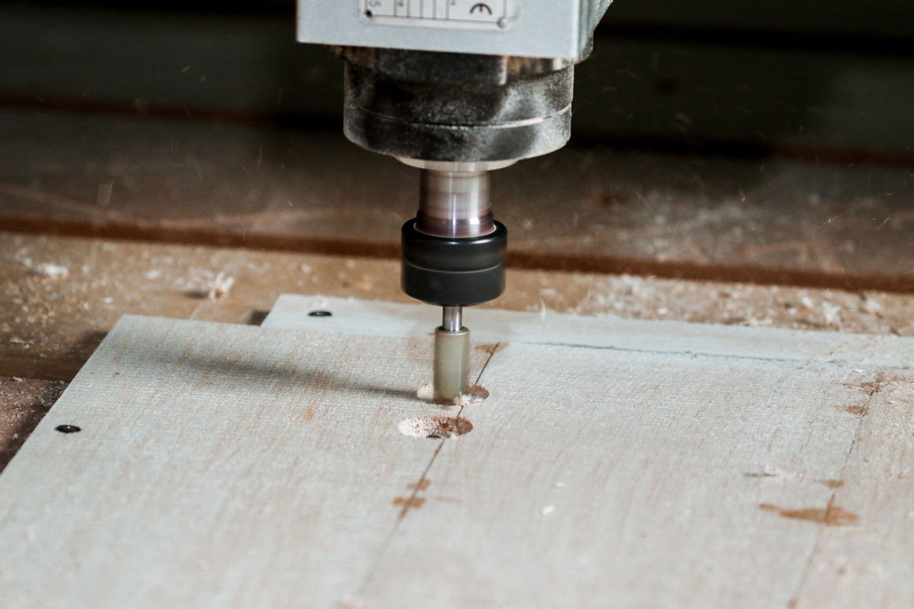
The part came off the router perfect. Clean edges, no tear-out, you're feeling pretty great about yourself.
Then you go to bolt it on and the M6 won't go through the hole.
The hole is 6 mm. The bolt is 6 mm. It should damn well fit!
It won't. Not ever. You need a bolt clearance hole — bigger than the bolt, so it slides through without threading. For M6 the standard answer is 6.6 mm. For M3 it's 3.4 mm. And then there's the second problem nobody mentions: the hole your router actually cuts isn't always the hole you drew.
Let's fix both.
Clearance hole sizes: metric
These come from ISO 273 — three fits, depending on how much wiggle you want. The ASME metric table lists the same numbers as close / normal / loose.
| Bolt | Close (fine) | Normal (medium) | Loose (coarse) | |---|---|---|---| | M3 | 3.2 mm | 3.4 mm | 3.6 mm | | M4 | 4.3 mm | 4.5 mm | 4.8 mm | | M5 | 5.3 mm | 5.5 mm | 5.8 mm | | M6 | 6.4 mm | 6.6 mm | 7.0 mm | | M8 | 8.4 mm | 9.0 mm | 10.0 mm | | M10 | 10.5 mm | 11.0 mm | 12.0 mm |
Normal is the default. Use close when the bolt is also locating the part. Use loose when you're lining up a bunch of holes across two parts and you want them to forgive you.
Heads up: a couple of charts floating around the internet have M3 at 3.35 and M6 at 6.5. The standard says 3.4 and 6.6.
Clearance hole sizes: imperial
Imperial has a weird thing going on. The ASME standard and the classic machine-shop charts don't agree — the shop charts are noticeably tighter.
Here's ASME B18.2.8, with millimetres because that's how I roll:
| Size | Close | Normal | |---|---|---| | #4 | #31 drill (~3.05 mm) | #30 (~3.26 mm) | | #6 | #23 (~3.91 mm) | #18 (~4.31 mm) | | #8 | #15 (~4.57 mm) | #9 (~4.98 mm) | | #10 | #5 (~5.22 mm) | #2 (~5.61 mm) | | 1/4" | 17/64" (~6.75 mm) | 9/32" (~7.14 mm) | | 5/16" | 21/64" (~8.33 mm) | 11/32" (~8.73 mm) | | 3/8" | 25/64" (~9.92 mm) | 13/32" (~10.32 mm) |
On a router, use the normal column. You'll see why in a minute.
Tap drill sizes
If the hole's getting threads instead of a bolt passing through, you need a tap drill — smaller than the bolt, so the tap has something to cut.
Metric has a beautiful shortcut: major diameter minus pitch. M6 × 1.0 → 5.0 mm. M8 × 1.25 → 6.75, round to 6.8. That gives you about 75% thread, which is what you want in aluminum, brass and plastics.
Steel's tougher to tap, so people drill a little bigger for a 50% thread. Per Little Machine Shop's chart:
| Thread | Aluminum / plastic (75%) | Steel (50%) | |---|---|---| | M3 × 0.5 | 2.5 mm | 2.7 mm | | M4 × 0.7 | 3.3 mm | 3.5 mm | | M5 × 0.8 | 4.2 mm | 4.5 mm | | M6 × 1.0 | 5.0 mm | 5.4 mm | | M8 × 1.25 | 6.8 mm | 7.2 mm | | M10 × 1.5 | 8.5 mm | 9.0 mm | | 1/4"-20 | #7 (5.11 mm) | 7/32" | | 10-32 | #21 (4.04 mm) | #18 |
Two material notes:
- Acrylic: go up one drill size from the chart, cool it, clear chips often — and don't count on a tapped acrylic hole to carry real load. If it gets unscrewed a lot, use an insert.
- Aluminum with a form tap (the kind that squishes threads instead of cutting them): those need a bigger hole. A 1/4"-20 form tap wants a #1 drill instead of the #7.
Counterbores for socket head cap screws
Want the head to sit flush? Counterbore it. Head sizes are ISO 4762; counterbore sizes are the Machinery's Handbook numbers.
| Screw | Head Ø | Head height | Counterbore Ø | Depth (flush) | |---|---|---|---|---| | M3 | 5.5 mm | 3.0 mm | 6.5 mm | 3.0 mm | | M4 | 7.0 mm | 4.0 mm | 8.25 mm | 4.0 mm | | M5 | 8.5 mm | 5.0 mm | 9.75 mm | 5.0 mm | | M6 | 10.0 mm | 6.0 mm | 11.25 mm | 6.0 mm | | M8 | 13.0 mm | 8.0 mm | 14.25 mm | 8.0 mm | | M10 | 16.0 mm | 10.0 mm | 17.25 mm | 10.0 mm |
Want it sunk a hair below the surface? Add half a millimetre or so to the depth.
Countersinks: 82° vs 90°
This one bites people constantly.
Metric flat heads are 90°. Imperial flat heads are 82°. Almost the same. Not the same.
- An 82° screw in a 90° hole only touches on its outer rim. All your clamping force is on a thin ring instead of the whole cone.
- A 90° screw in an 82° hole sits proud. And no amount of torque pulls it flush — you'll just crush the head.
On a router, that means matching your V-bit to your screw. A 90° V-bit for metric flat heads. An 82° countersink for imperial.
Why your router cuts the wrong size hole
Okay. Here's the part none of the charts tell you.
First: an endmill is a bad drill. It isn't designed to plunge straight down. For most holes, use an endmill smaller than the hole and a circular pocket (or helix) toolpath. That's how the Shapeoko community guide says to do it, and it's how the pros do it too.
Second: your 1/4" bit isn't 1/4". A "1/4 inch" endmill can be anywhere from about 0.245" to 0.255". Measure yours with calipers and type the real number into your CAM.
Third: runout and deflection. A bit that wobbles even a little cuts a bigger hole than its diameter. A long, skinny bit bends away from the cut and makes holes smaller. Fixes: shortest stickout you can get away with, and a finishing pass — rough it out, then come back for a light last lap.
Fourth: small holes come out small. Your CAM sets the feed rate at the center of the tool. In a tiny hole, the cutting edge on the outside is moving way faster than you think, and the bit gets pushed around. Slow down for small holes.
The real fix for all four:
Cut a test coupon. Holes at nominal, +0.1 mm, +0.2 mm. Try your actual bolt in each one. Keep the winner.
Then write that offset down next to that bit and that material, because you are not going to remember that shit in three months. That's literally what the Machine Setups Repository is for — every machine, every material, your real numbers, one click away.
Nut pockets need corner relief
Round bits can't cut sharp inside corners. They leave a radius.
That's a problem for a hex nut pocket. I ran the geometry: with a 1/4" bit, even with 0.2 mm of extra room, the rounded corners of a hex pocket won't clear an M4 through M10 nut. The nut's corners just hit. A 1/8" bit just barely clears — and a nut with especially sharp corners can still bind.
Two fixes:
- Dogbones or T-bones at each corner — little overcuts that let the corner of the nut (or the mating part) sit all the way in. Vectric's docs describe the idea well, and a common rule is a corner radius at least 1.1× your tool radius.
- Use a square nut in a slot. Square nuts don't care about your corner radius as much, and they can't spin. (More on why square nuts are underrated.)
Bolting into wood
Threads cut straight into wood strip out. Plywood especially. If it's getting assembled more than once, give it real metal threads:
- Threaded inserts. E-Z Lok's chart calls for a 25/64" (9.92 mm) hole for their 1/4"-20 or M6 knife-thread inserts (hardwood), and 23/64" (9.13 mm) for their hex-drive inserts (pine, MDF, plywood). Their own advice: test first, and go slightly bigger in hardwood so it doesn't split. Their brochure has every size.
- T-nuts. Fine in shear, weak in tension — they can pull through from the back. Screw-on T-nuts are better.
- Cross dowels (barrel nuts) for flat-pack furniture. Strong, invisible, and very CNC-friendly. Drill to whatever the hardware's spec says — sizes vary by brand.
What about lasers?
Same charts, with one twist: the laser beam has width (kerf), so holes grow by roughly one kerf width in diameter. If you need a close-fit hole, shrink the drawn hole a touch. For normal clearance, it usually doesn't matter.
And if you're building laser-cut panels that bolt together, look up the T-slot joint — a square nut trapped in a T-shaped slot in one panel, a screw coming through the other. No glue, fully knock-down, and it's held a lot of flat-pack together.
Get the numbers without the charts
Our bolt generator, the Nasty Bastard, hands you the tap drill and clearance hole for any metric or imperial size, plus a printable drill chart to stick on the wall next to your machine. For counterbores and countersinks, the tables above have you covered.
So what are you bolting together first — and what's your bit actually measuring?
Frequently asked questions
- What size clearance hole for an M6 bolt?
- 6.6 mm is the standard normal (medium) fit per ISO 273. Use 6.4 mm for a close fit or 7.0 mm for a loose fit. For M3 the normal clearance hole is 3.4 mm, M4 is 4.5 mm, M5 is 5.5 mm, M8 is 9.0 mm, and M10 is 11.0 mm.
- What size clearance hole for a 1/4-20 bolt?
- Per ASME B18.2.8, a 17/64 in drill (about 6.75 mm) for a close fit or a 9/32 in drill (about 7.14 mm) for a normal fit. Older shop charts list tighter sizes, so on a CNC router the normal fit is the safer pick.
- How do I calculate a metric tap drill size?
- Subtract the pitch from the major diameter. M6 x 1.0 needs a 5.0 mm drill, M8 x 1.25 needs about 6.8 mm. That gives roughly a 75% thread, which suits aluminum and plastics. For steel, go slightly larger for about a 50% thread.
- Why are holes cut on my CNC router the wrong size?
- Endmills aren't real drills, actual bit diameters vary from the nominal size, runout makes holes bigger, and deflection makes them smaller. Use a smaller bit with a circular pocket toolpath, enter your measured bit diameter in CAM, add a finishing pass, and cut a test coupon to find your offset.
- What angle is a countersink for flat head screws?
- 90 degrees for metric flat head screws and 82 degrees for imperial (inch) flat head screws. Mixing them up means the screw either bears only on its outer rim or sits proud and can't be pulled flush.